Nhiều bạn liên hệ DevOps VietNam hỏi cách xây dựng hạ tầng kiến trúc Cloud (AWS, Azure, GCP,…) hay Các DevOps Tools (K8s, Elastic,…) hoặc các nền tảng hạ tầng (như OpenStack) thành Diagram bằng code làm sao cho hiệu quả, nhanh chóng và đơn giản.
Công cụ thì rất nhiều nhưng sau đây DevOps VietNam sẽ hướng dẫn mọi người cách xây dựng hạ tầng kiến trúc Cloud/DevOps với Diagrams một công cụ mạnh mẽ nhưng vẫn đảm bảo đơn giản dễ sử dụng (kèm code template cụ thể).
Chỉ cần vài bước setup thêm một file code với câu lệnh chạy là bạn hoàn toàn có thể tạo ra được hạ tầng kiến trúc như này:
Diagrams – Công Cụ Xây dựng Sơ Đồ Hạ Tầng Cloud
Diagrams là một thư viện Python mạnh mẽ cho phép bạn dễ dàng tạo ra các sơ đồ hạ tầng kiến trúc, đặc biệt là cho các kiến trúc AWS, Azure, Google Cloud, và nhiều dịch vụ khác. Với Diagrams, bạn có thể tự động hóa việc xây dựng sơ đồ hạ tầng một cách nhanh chóng và hiệu quả mà không cần phải sử dụng các công cụ đồ họa phức tạp. Đây là một công cụ rất hữu ích dành cho các DevOps, kiến trúc sư hệ thống và những ai làm việc với cloud/DevOps infrastructure.
Ngoài ra Diagrams có thể xây dựng đươc rất nhiều các hạ tầng kiến trúc khác như K8s, AlibabaCloud, OpenStack, Elastic, Firebase,…
Chi tiết bạn có thể tham khảo tài liệu chính thức: About Diagrams
Cài đặt và thiết lập Diagrams
Ở đây, devops.vn sẽ hướng dẫn bạn cài đặt trên Ubuntu OS. Đối với các distro Linux khác, bạn cũng có thể làm theo cách tương tự.
Thông thường khi cài đặt Ubuntu server đầy đủ tài nguyên sẽ có sẵn python nhưng nếu server của bạn chưa có bạn có thể cài đặt bằng rất nhiều cách tham khảo tại trang chủ python, hoặc ví dụ:
sudo apt install python3-pip -yCập nhật danh sách gói phần mềm của hệ thống
apt-get update -yCài đặt công cụ xây dựng sơ đồ Graphviz và thư viện phát triển
sudo apt install graphviz libgraphviz-dev -yCài đặt pip cho Python 3 (nếu chưa có) để quản lý các thư viện Python
apt install python3-pip -yCài đặt pipenv để quản lý môi trường ảo và các gói phụ thuộc trong Python
pip3 install pipenvTạo thư mục cho dự án xây dựng sơ đồ
mkdir cloud-diagram && cd cloud-diagramCài đặt thư viện requests trong môi trường ảo để gửi yêu cầu HTTP
pipenv install requestsCài đặt thư viện diagrams trong môi trường ảo để xây dựng sơ đồ hạ tầng Cloud/DevOps
pipenv install diagramsKích hoạt môi trường ảo để làm việc với các gói đã cài đặt (pipenv shell)
pipenv shellThực hành Xây Dựng Hạ Tầng Kiến Trúc Cloud/DevOps
Ở phần này, chúng ta sẽ bắt đầu thực hành tạo ra các sơ đồ hạ tầng kiến trúc hạ tầng Cloud/DevOps một cách trực quan bằng công cụ Diagrams. Chúng ta sẽ đi từ những ví dụ đơn giản đến phức tạp hơn, nhằm giúp bạn hình dung cách mô hình hóa hệ thống thực tế trên các nền tảng như AWS, Azure, GCP, và áp dụng linh hoạt vào công việc thiết kế, trình bày giải pháp kỹ thuật.
Và phần dưới mình sẽ lưu ý các phần để giúp bạn dễ hàng xây dựng hạ tầng kiến trúc Cloud/DevOps với diagram dễ dàng hơn.
AWS
Tạo file aws_web_service_diagram.py
from diagrams import Diagram
from diagrams.aws.compute import EC2
from diagrams.aws.database import RDS
from diagrams.aws.network import ELB

with Diagram("AWS Web Service", show=False):
    ELB("lb") >> EC2("web") >> RDS("userdb")
Chạy lệnh tạo diagram
python aws_web_service_diagram.pyVà sẽ được kết quả file ảnh với tên aws_web_service.png như sau:

Azure
Tạo file aruze_web_service_diagram.py
from diagrams import Diagram
from diagrams.azure.compute import AppServices
from diagrams.azure.network import LoadBalancers
from diagrams.azure.storage import StorageAccounts

with Diagram("Azure Web Service", show=False):
    lb = LoadBalancers("load balancer")
    web_server = AppServices("web server")
    storage = StorageAccounts("azure storage")

    lb >> web_server >> storage
Chạy lệnh tạo diagram
python aruze_web_service_diagram.pyVà sẽ được kết quả file ảnh với tên aruze_web_service.png như sau:

GCP
Tạo file gcp_web_service_diagram.py
from diagrams import Diagram
from diagrams.gcp.compute import ComputeEngine
from diagrams.gcp.network import LoadBalancing
from diagrams.gcp.storage import Storage

with Diagram("GCP Web Service", show=False):
    lb = LoadBalancing("load balancer")
    web_server = ComputeEngine("web server")
    storage = Storage("cloud storage")

    lb >> web_server >> storage
Chạy lệnh tạo diagram
python gcp_web_service_diagram.pyVà sẽ được kết quả file ảnh với tên gcp_web_service.png như sau:
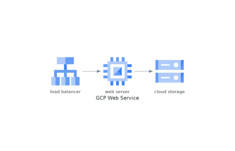
Bạn có thể thấy là hạ tầng kiến trúc Cloud sẽ được tạo nên nhanh chóng và đảm bảo thống nhất, đồng bộ và dễ dàng quản lý.
Các Template Và Lưu Ý Khi Sử Dụng Diagrams
Theo tài liệu chính thức và thời buổi AI rất phát triển bạn hoàn toàn có thể dành một chút thời gian nghiên cứu và dễ dàng xây dựng được các diagram theo mong muốn. Tuy nhiên, để đầy đủ hơn DevOps VietNam cũng có vài lưu ý hữu ích để giúp bạn nhanh chóng nắm bắt được công cụ này và sau đây là một số code template để bạn tham khảo.
Cấu Hình Đồ Thị (background, font size, hướng sơ đồ,…).
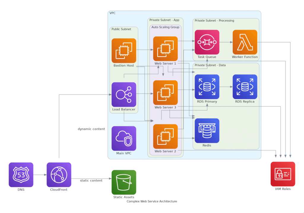
Đây là một template xây dựng hạ tầng kiến trúc của một ứng dụng web phân tán, có tính sẵn sàng cao và khả năng mở rộng
from diagrams import Cluster, Diagram, Edge
from diagrams.aws.compute import EC2, Lambda
from diagrams.aws.database import RDS, ElastiCache
from diagrams.aws.network import ELB, Route53, CloudFront, VPC, PrivateSubnet, PublicSubnet
from diagrams.aws.storage import S3
from diagrams.aws.security import IAM
from diagrams.aws.integration import SQS

graph_attr = {
    "fontsize": "12",
    "bgcolor": "white",
    "pad": "0.5",
    "rankdir": "LR"
}

with Diagram("Complex Web Service Architecture", show=False, direction="LR", graph_attr=graph_attr):
    # DNS and CDN
    dns = Route53("DNS")
    cdn = CloudFront("CloudFront")

    # VPC Cluster
    with Cluster("VPC"):
        vpc = VPC("Main VPC")

        # Public Subnet
        with Cluster("Public Subnet"):
            elb = ELB("Load Balancer")
            bastion = EC2("Bastion Host")

        # Private Subnet - Application Layer
        with Cluster("Private Subnet - App"):
            with Cluster("Auto Scaling Group"):
                web_servers = [EC2("Web Server 1"),
                              EC2("Web Server 2"),
                              EC2("Web Server 3")]

        # Private Subnet - Data Layer
        with Cluster("Private Subnet - Data"):
            rds_primary = RDS("RDS Primary")
            rds_replica = RDS("RDS Replica")
            cache = ElastiCache("Redis")

        # Private Subnet - Background Processing
        with Cluster("Private Subnet - Processing"):
            queue = SQS("Task Queue")
            worker = Lambda("Worker Function")

    # Storage
    s3 = S3("Static Assets")

    # Security
    security = IAM("IAM Roles")

    # Connections
    dns >> cdn
    cdn >> Edge(label="static content") >> s3
    cdn >> Edge(label="dynamic content") >> elb
    elb >> web_servers
    bastion >> web_servers
    web_servers >> rds_primary
    rds_primary >> rds_replica
    web_servers >> cache
    web_servers >> queue
    queue >> worker
    web_servers >> security
    worker >> security
Bạn có thể nhìn thấy thành phần graph_attr chính xác là phần cấu hình đồ thị, với tùy chọn "rankdir": "LR" sẽ xây dựng biểu đồ Left to Right (Biều đồ theo hạ tầng từ trái sang phải) như sau:
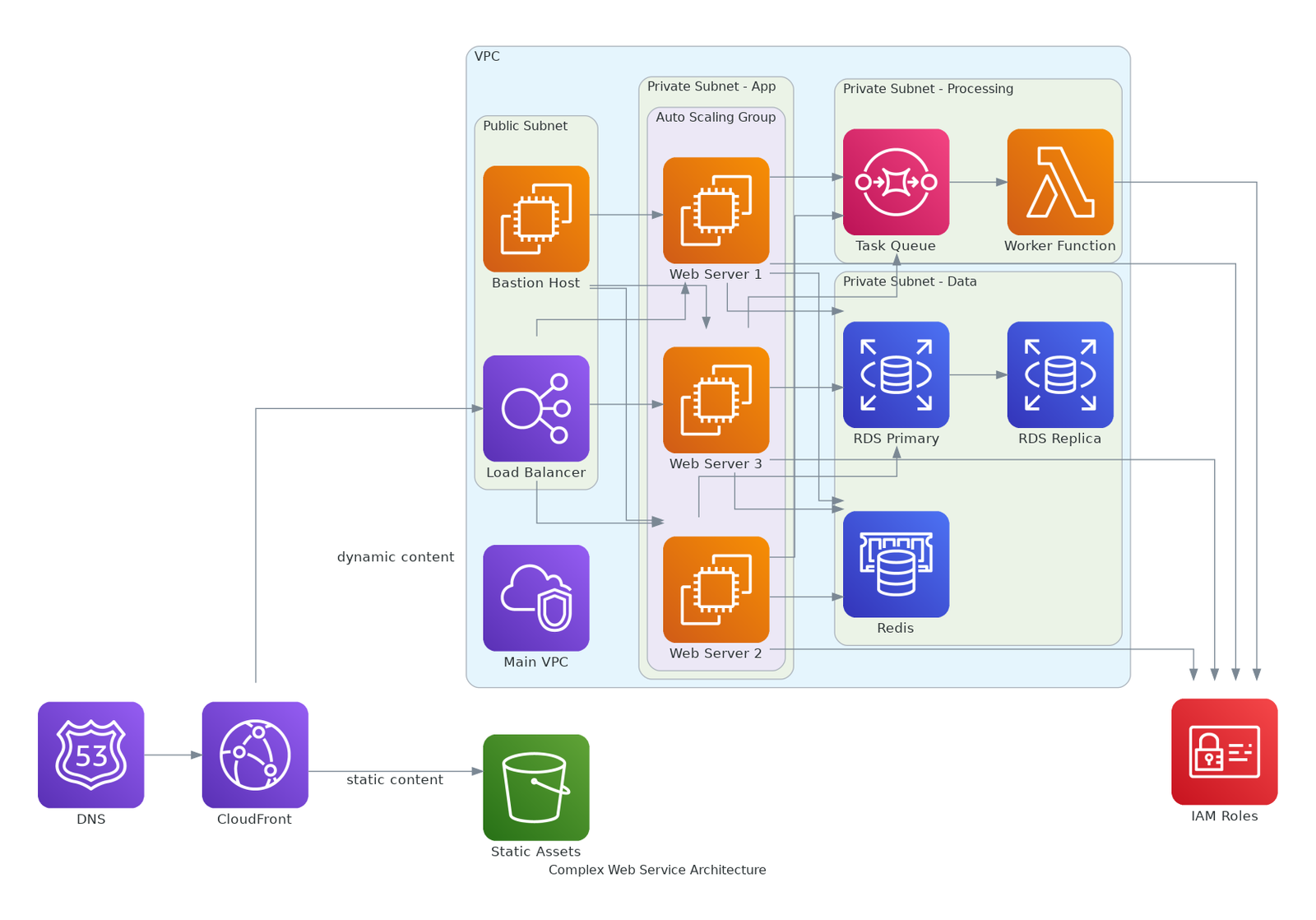
Nhưng chỉ cần đổi thành "rankdir": "TB" sẽ xây dựng biểu đồ Top to Bottom (Biều đồ theo hạ tầng từ trên xuống dưới) như sau:

node_attr
Quy định mặc định cho các node (tức là các dịch vụ AWS, Azure, Database…).
Ví dụ:
node_attr = {
    "style": "filled",
    "shape": "box",
    "fillcolor": "lightgrey",
    "fontsize": "10"
}
Giải thích:
- “shape”: “box” : để icon dịch vụ trong ô vuông.
- “fillcolor” : màu nền mỗi node.
- “style”: “filled” : bắt buộc nếu muốn màu nền fill vào node.
edge_attr
Điều chỉnh mặc định đường nối giữa các node.
Ví dụ:
edge_attr = {
    "color": "gray",
    "style": "dashed",
    "fontsize": "10"
}
Giải thích:
- “style”: “dashed” : nét đứt, dùng cho kết nối không trực tiếp hoặc backup link.
- “color” : chỉnh màu line cho dễ nhìn flow.
Cluster
Gom nhóm các dịch vụ vào cùng 1 block.
Ví dụ:
with Cluster("VPC Public Subnet"):
    ec2 = EC2("Web Server")
    lb = ELB("Load Balancer")
Giải thích:
- Cần đặt tên cho Cluster rõ ràng.
- Các dịch vụ bên trong sẽ được tự căn chỉnh hợp lý.
Các Đối Tượng Service
Import đúng service mới vẽ được.
Ví dụ:
from diagrams.aws.compute import EC2
from diagrams.aws.network import ELB
from diagrams.aws.database import RDS
Tạo Kết Nối Giữa Các Node
Cách kết nối trong hạ tầng kiến trúc, Dùng >> hoặc << để chỉ chiều đi của flow.
Ví dụ:
ec2 >> rds
ec2 >> elb
Tùy Chỉnh Riêng Từng Kết Nối
Nếu muốn từng đường nối custom thêm:
Ví dụ:
ec2 >> Edge(color="red", style="dotted") >> rdsXuất File
Khi xong sơ đồ, nó tự xuất file .png hoặc .svg theo tên bạn đặt.
Ví dụ:
with Diagram("Simple Web Service", show=False, filename="web_service", graph_attr=graph_attr):
    ...
Ghi Chú Riêng
Nếu sơ đồ lớn, nên comment rõ từng phần để người đọc sau dễ hiểu.
Ví dụ:
# Create public subnet
with Cluster("Public"):
    ...

# Create database tier
with Cluster("Database"):
    ...
Áp Dụng Các Thành Phần
Đây là code khi đã sửa đổi từ sample phía trên khi sử dụng các thành phần cấu hình:
from diagrams import Diagram, Cluster, Edge
from diagrams.aws.compute import EC2
from diagrams.aws.database import RDS
from diagrams.aws.network import ELB
# Cấu hình tổng thể cho sơ đồ
graph_attr = {
"fontsize": "16",
"bgcolor": "white",
"pad": "0.5",
"rankdir": "LR"
}
node_attr = {
"style": "filled",
"shape": "box",
"fillcolor": "lightblue",
"fontsize": "12"
}
edge_attr = {
"color": "gray",
"fontsize": "10"
}
# Bắt đầu vẽ Diagram
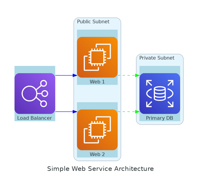
with Diagram(
"Simple Web Service Architecture",
show=False,
filename="simple_web_service",
graph_attr=graph_attr,
node_attr=node_attr,
edge_attr=edge_attr
):
# Load Balancer ngoài Internet
lb = ELB("Load Balancer")
# Cụm Public Subnet
with Cluster("Public Subnet"):
web_servers = [EC2("Web 1"), EC2("Web 2")]
# Cụm Database Subnet
with Cluster("Private Subnet"):
db = RDS("Primary DB")
# Kết nối giữa các thành phần
lb >> Edge(color="blue") >> web_servers
web_servers >> Edge(color="green", style="dashed") >> dbKết quả sẽ như sau:
Lưu Ý Về Phiên Bản
Có những thành phần phiên bản hiện tại của bạn sẽ chưa phù hợp (hoặc thiếu, hoặc bị thay đổi) bạn hãy chú ý upgrade phiên bản để đảm bảo sử dụng đúng tài liệu chính thức nhé.
Template Mẫu Tham Khảo
Bạn có thể tham khảo một số mẫu code template xây dựng hạ tầng kiến trúc Cloud/DevOps dưới đây của DevOps VietNam để nghiên cứu thêm cộng với tài liệu chính thức và sự trợ giúp của AI giờ đã rất mạnh mẽ giúp nhanh chóng nắm bắt cách sử dụng.
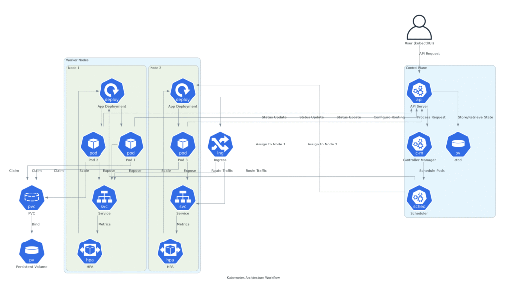
Kubernetes Workflow
Code:
from diagrams import Cluster, Diagram, Edge
from diagrams.k8s.clusterconfig import HPA
from diagrams.k8s.compute import Pod, Deployment
from diagrams.k8s.controlplane import API, Scheduler, ControllerManager
from diagrams.k8s.storage import PV, PVC
from diagrams.k8s.network import Service, Ingress
from diagrams.onprem.client import User

# Diagram attributes for better visualization
graph_attr = {
    "fontsize": "12",
    "bgcolor": "white",
    "pad": "0.5",
    "rankdir": "TB"  # Top to Bottom direction
}

with Diagram("Kubernetes Architecture Workflow", show=False, direction="TB", graph_attr=graph_attr):
    # External User (kubectl or UI)
    user = User("User (kubectl/UI)")

    # Control Plane Cluster
    with Cluster("Control Plane"):
        api_server = API("API Server")
        etcd = PV("etcd")
        scheduler = Scheduler("Scheduler")
        controller_manager = ControllerManager("Controller Manager")

    # Worker Nodes Cluster
    with Cluster("Worker Nodes"):
        with Cluster("Node 1"):
            deployment_1 = Deployment("App Deployment")
            pods_1 = [Pod("Pod 1"), Pod("Pod 2")]
            service_1 = Service("Service")
            hpa_1 = HPA("HPA")

        with Cluster("Node 2"):
            deployment_2 = Deployment("App Deployment")
            pods_2 = [Pod("Pod 3")]
            service_2 = Service("Service")
            hpa_2 = HPA("HPA")

    # Networking
    ingress = Ingress("Ingress")

    # Persistent Storage
    pvc = PVC("PVC")
    pv = PV("Persistent Volume")

    # Workflow Connections
    # Step 1: User sends request to API Server
    user >> Edge(label="API Request") >> api_server

    # Step 2: API Server interacts with etcd to store/retrieve state
    api_server >> Edge(label="Store/Retrieve State") >> etcd

    # Step 3: API Server notifies Controller Manager
    api_server >> Edge(label="Process Request") >> controller_manager

    # Step 4: Controller Manager coordinates with Scheduler
    controller_manager >> Edge(label="Schedule Pods") >> scheduler

    # Step 5: Scheduler assigns Pods to Nodes via Deployments
    scheduler >> Edge(label="Assign to Node 1") >> deployment_1
    scheduler >> Edge(label="Assign to Node 2") >> deployment_2

    # Step 6: Deployments manage Pods
    deployment_1 >> pods_1
    deployment_2 >> pods_2

    # Step 7: Services expose Pods
    pods_1 >> Edge(label="Expose") >> service_1
    pods_2 >> Edge(label="Expose") >> service_2

    # Step 8: Ingress routes traffic to Services
    api_server >> Edge(label="Configure Routing") >> ingress
    ingress >> Edge(label="Route Traffic") >> [service_1, service_2]

    # Step 9: Horizontal Pod Autoscaler adjusts Deployments
    service_1 >> Edge(label="Metrics") >> hpa_1
    service_2 >> Edge(label="Metrics") >> hpa_2
    hpa_1 >> Edge(label="Scale") >> deployment_1
    hpa_2 >> Edge(label="Scale") >> deployment_2

    # Step 10: Pods use Persistent Storage
    pods_1 >> Edge(label="Claim") >> pvc
    pods_2 >> Edge(label="Claim") >> pvc
    pvc >> Edge(label="Bind") >> pv

    # Step 11: Pods report status back to API Server
    pods_1 >> Edge(label="Status Update") >> api_server
    pods_2 >> Edge(label="Status Update") >> api_server
Kết quả:
Hạ Tầng Kiến Trúc Microservice trên AWS
Code:
from diagrams import Cluster, Diagram, Edge
from diagrams.aws.compute import EC2, Lambda
from diagrams.aws.database import RDS
from diagrams.aws.network import APIGateway, Route53
from diagrams.aws.storage import S3
from diagrams.aws.integration import SQS, SNS
from diagrams.aws.security import IAM
from diagrams.onprem.client import User

# Diagram attributes for better visualization
graph_attr = {
    "fontsize": "12",
    "bgcolor": "white",
    "pad": "0.5",
    "rankdir": "TB"  # Top to Bottom direction
}

with Diagram("Microservice Architecture on AWS", show=False, direction="TB", graph_attr=graph_attr):
    # External User
    user = User("Client (Web/Mobile)")

    # DNS and API Gateway
    dns = Route53("DNS")
    api_gateway = APIGateway("API Gateway")

    # Microservices Cluster
    with Cluster("Microservices"):
        # User Service
        with Cluster("User Service"):
            user_service = EC2("User API")
            user_db = RDS("User DB")

        # Order Service
        with Cluster("Order Service"):
            order_service = EC2("Order API")
            order_db = RDS("Order DB")

        # Payment Service
        with Cluster("Payment Service"):
            payment_service = Lambda("Payment Function")
            payment_db = RDS("Payment DB")

    # Async Processing
    queue = SQS("Message Queue")
    notification = SNS("Notification Service")

    # Storage
    storage = S3("Static Assets")

    # Security
    security = IAM("IAM Roles")

    # Workflow Connections
    # Step 1: User sends request via DNS to API Gateway
    user >> Edge(label="HTTP Request") >> dns
    dns >> api_gateway

    # Step 2: API Gateway routes to Microservices
    api_gateway >> Edge(label="User Requests") >> user_service
    api_gateway >> Edge(label="Order Requests") >> order_service
    api_gateway >> Edge(label="Payment Requests") >> payment_service

    # Step 3: Microservices interact with their databases
    user_service >> Edge(label="Read/Write") >> user_db
    order_service >> Edge(label="Read/Write") >> order_db
    payment_service >> Edge(label="Read/Write") >> payment_db

    # Step 4: Microservices communicate asynchronously
    user_service >> Edge(label="Order Event") >> queue
    order_service >> Edge(label="Process Order") >> queue
    payment_service >> Edge(label="Payment Event") >> queue
    queue >> Edge(label="Notify") >> notification

    # Step 5: Microservices use storage for static assets
    user_service >> Edge(label="Store/Retrieve") >> storage
    order_service >> Edge(label="Store/Retrieve") >> storage

    # Step 6: Security
    user_service >> Edge(label="Auth") >> security
    order_service >> Edge(label="Auth") >> security
    payment_service >> Edge(label="Auth") >> security
Kết quả:

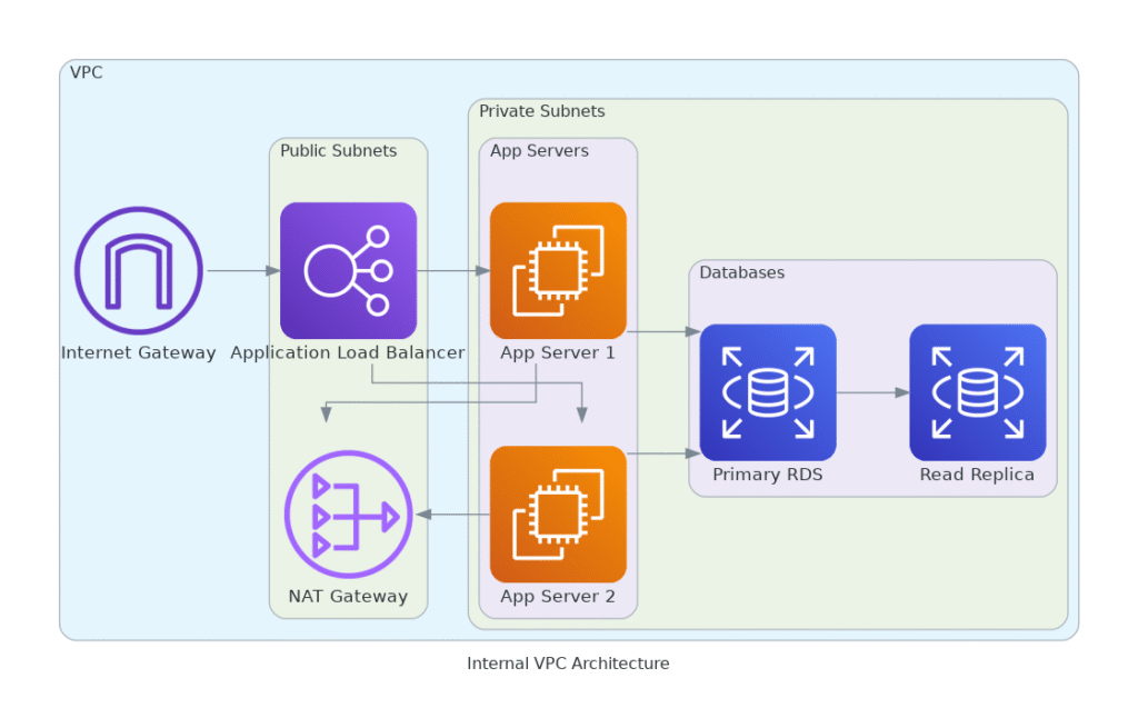
Internal VPC Architecture
Code:
from diagrams import Cluster, Diagram
from diagrams.aws.network import VPC, InternetGateway, NATGateway, RouteTable, ELB, PrivateSubnet, PublicSubnet
from diagrams.aws.compute import EC2
from diagrams.aws.database import RDS
from diagrams.aws.network import CloudFront

# Diagram attributes for better visualization
graph_attr = {
    "fontsize": "12",
    "bgcolor": "white",
    "pad": "0.5",
    "rankdir": "LR"
}

with Diagram("Internal VPC Architecture", show=False, direction="LR", graph_attr=graph_attr):
    with Cluster("VPC"):
        igw = InternetGateway("Internet Gateway")

        with Cluster("Public Subnets"):
            alb = ELB("Application Load Balancer")
            nat_gw = NATGateway("NAT Gateway")

        with Cluster("Private Subnets"):
            with Cluster("App Servers"):
                app_servers = [EC2("App Server 1"),
                               EC2("App Server 2")]

            with Cluster("Databases"):
                db_primary = RDS("Primary RDS")
                db_replica = RDS("Read Replica")

        # Connections
        igw >> alb
        alb >> app_servers
        app_servers >> db_primary
        db_primary >> db_replica

        # NAT Gateway hỗ trợ app servers ra ngoài nếu cần
        app_servers >> nat_gw
Kết quả:
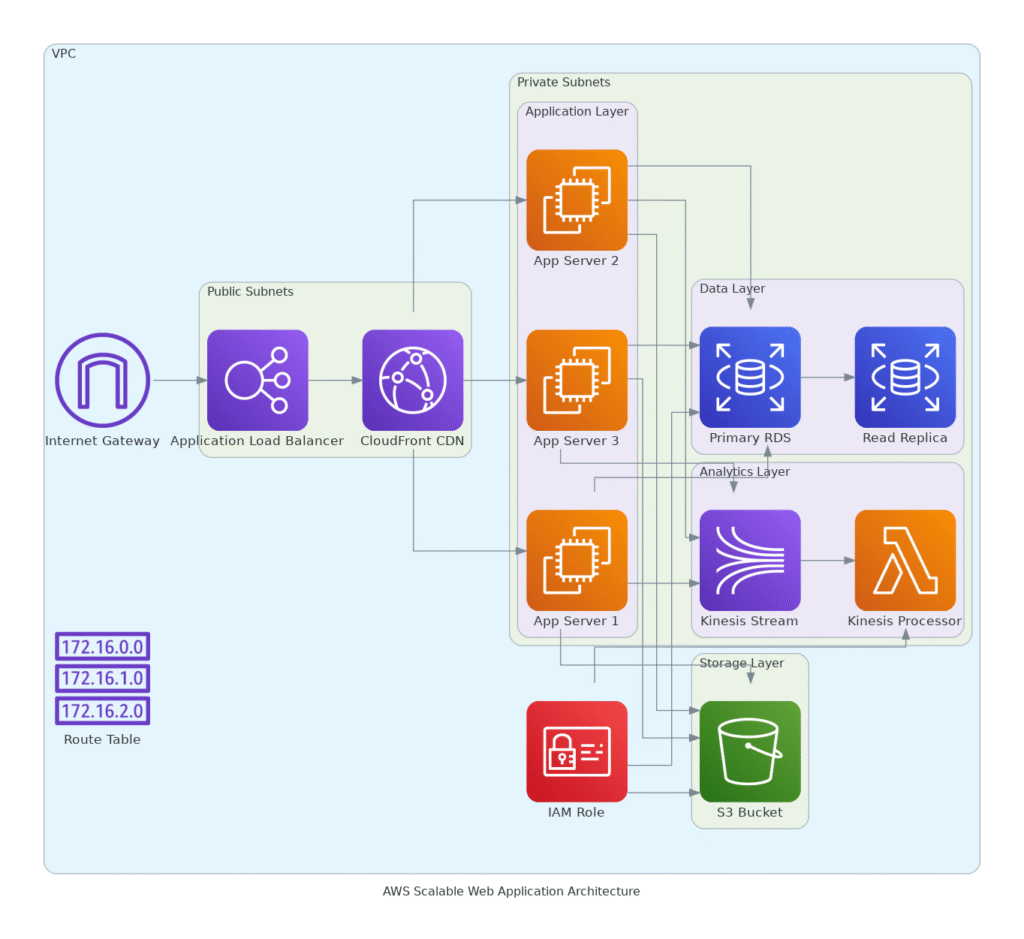
AWS Scalable Web Application Architecture
Code:
from diagrams import Cluster, Diagram
from diagrams.aws.compute import EC2, Lambda
from diagrams.aws.database import RDS
from diagrams.aws.network import VPC, InternetGateway, RouteTable, ELB, CloudFront
from diagrams.aws.security import IAM
from diagrams.aws.storage import S3
from diagrams.aws.analytics import Kinesis

# Diagram attributes for better visualization
graph_attr = {
    "fontsize": "12",
    "bgcolor": "white",
    "pad": "0.5",
    "rankdir": "LR"
}

with Diagram("AWS Scalable Web Application Architecture", show=False, direction="LR", graph_attr=graph_attr):
    with Cluster("VPC"):
        igw = InternetGateway("Internet Gateway")
        route_table = RouteTable("Route Table")

        with Cluster("Public Subnets"):
            alb = ELB("Application Load Balancer")
            cloudfront = CloudFront("CloudFront CDN")

        with Cluster("Private Subnets"):
            with Cluster("Application Layer"):
                app_servers = [EC2("App Server 1"),
                               EC2("App Server 2"),
                               EC2("App Server 3")]

            with Cluster("Data Layer"):
                db_primary = RDS("Primary RDS")
                db_replica = RDS("Read Replica")

            with Cluster("Analytics Layer"):
                kinesis_stream = Kinesis("Kinesis Stream")
                kinesis_processor = Lambda("Kinesis Processor")

        with Cluster("Storage Layer"):
            s3_bucket = S3("S3 Bucket")

        # IAM Role to interact with resources securely
        iam_role = IAM("IAM Role")

        # Connections
        igw >> alb
        alb >> cloudfront
        cloudfront >> app_servers

        app_servers >> db_primary
        db_primary >> db_replica

        # Analytics Pipeline
        app_servers >> kinesis_stream
        kinesis_stream >> kinesis_processor

        # S3 Bucket for data storage
        app_servers >> s3_bucket

        # IAM role permissions
        iam_role >> db_primary
        iam_role >> s3_bucket
        iam_role >> kinesis_processor
Kết quả:
Kết luận
Trên đây là những kiến thức nhanh mà bạn có thể sử dụng để xây dựng hạ tầng kiến trúc Cloud/DevOps nhanh chóng hiệu quả và vẫn đảm bảo đơn giản. Tất nhiên còn rất nhiều công cụ hữu ích mạnh mẽ khác. Nếu mọi người có nhu cầu có thể gửi yêu cầu về DevOps VietNam chúng tôi sẽ hướng dẫn cụ thể.